
Mach Zehnder interferometric planar Doppler velocimetry (MZI-PDV)
Introduction
PDV requires some form of filter to act as a frequency-to-intensity transducer; usually this is a molecular absorption cell, typically Iodine vapour; however an interferometric filter can potentially be used in a PDV system. This has several advantages, the choice of laser source is now not limited by the availability of a suitable absorption line so any high power, narrow linewidth laser can be used. A second important advantage is that the velocity sensitivity and range can be varied using an interferometric filter, potentially allowing lower/higher velocities to be measured than with a conventional PDV system.
Theory
Figure 1 shows the arrangement of an unbalanced Mach-Zehnder PDV interferometer (MZI-PDV). A laser light sheet, of frequency $$\nu$$, illuminates the object plane $$\Sigma$$ located in the flow. Light scattered from particles seeded in the flow is collected and coupled into the interferometer. Frequency variations caused by the Doppler shift are converted into variations in the recorded intensities on CCD detectors located at $$\Sigma$$’, and $$\Sigma$$’’.
The scattered light coming from the object plane $$\Sigma$$ is collimated by lens L1 and then divided by BS1 (beam-splitter, 50:50 split ratio) into two beams of equal intensity, which follow paths l1 and l2. The light in path l1 is turned at mirror M2 and prism P2 before being split by BS2 (beam-splitter, 50:50 split ratio) and imaged onto the two detectors located at $$\Sigma$$’, and $$\Sigma$$’’ using lenses L2 and L3. The second path, l2 passes through a glass block G, with a length l and refractive index n. The light is retroreflected by prism P1, making a second pass through the glass block. It is then turned at mirror, M1 and recombined with the light in the first path at BS2.
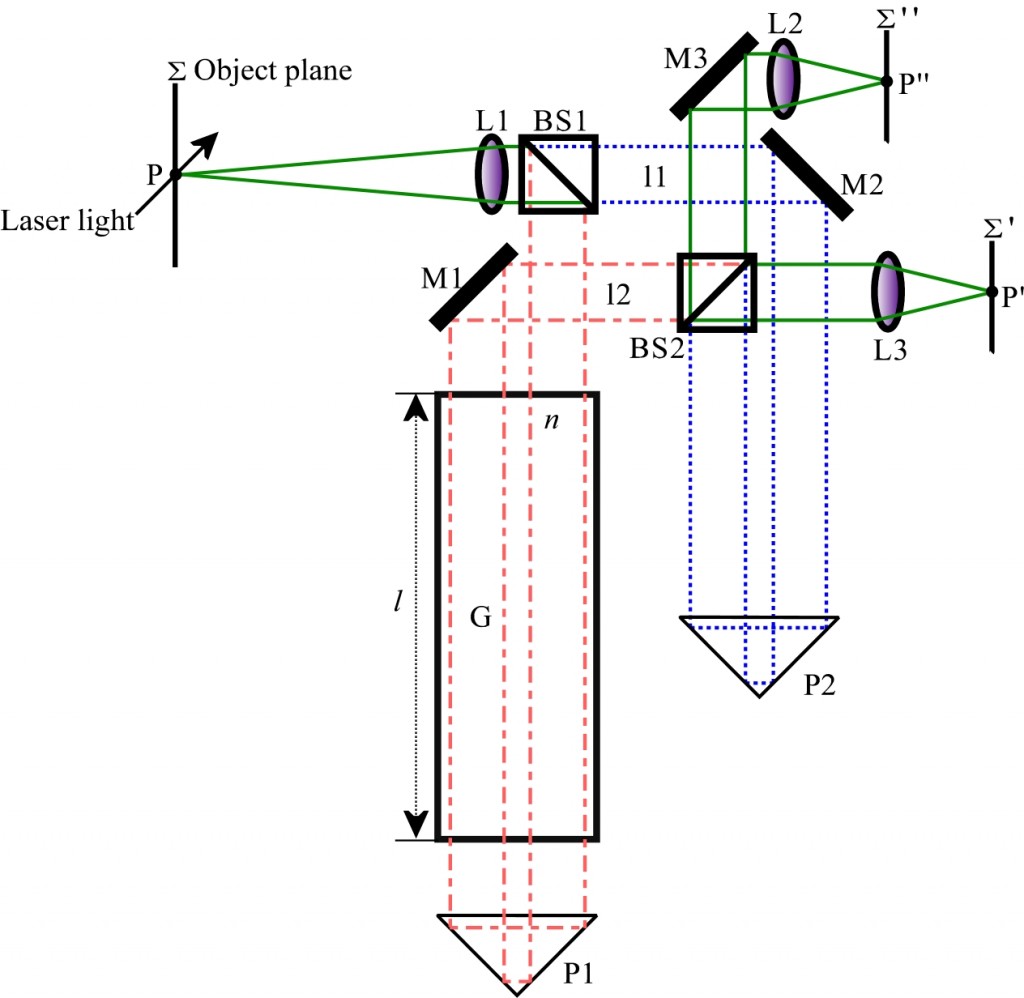
Figure 1 An unbalanced Mach-Zehnder interferometer for PDV. The beam paths are shown in different colours path in blue (dashed), path in red (dot-dashed) and combined paths in green (solid).
Therefore, for a Mach-Zehnder interferometer, the normalised intensity $${I}_{N}$$ can be found by taking the difference of the two intensities over the sum. This can then be expressed as:
$$!{I}_{N}=\frac{{I}_{1}-{I}_{2}}{{I}_{1}+{I}_{2}}\propto V\cdot\cos {\left(\Delta\phi\right)}$$
Where V is the interference fringe visibility determined by the transmission performance of the whole optical set-up. The normalised intensity, $${I}_{N}$$, is a function only of the phase difference $$\Delta\phi$$ and is independent of the original input intensity. The phase difference $$\Delta\phi$$ is a function of the optical path difference ($$\Delta$$I) between the two arms, the light source frequency (n) and the free space speed of light (c). Any Doppler shift will cause a change in the phase difference between the two arms leading to a change in the normalised intensity. Therefore by measuring $${I}_{N}$$ the phase change, Doppler shift and flow velocity can be found
$$!\Delta\phi=\frac{2\pi\Delta I}{c}\nu$$
$$!\Delta\nu=\frac{c}{2\pi\Delta I}\Delta\left(\Delta\phi\right)$$
A second method of processing the results is to skeletonise the fringe images and measure the shift between flow on and off fringe positions, this provides velocity measurements along the fringe locations.
Time-averaged MZI-PDV system
Figure 2 shows the experimental arrangement of the MZI-PDV system constructed at Cranfield. The illuminating laser was a tuneable argon-ion laser incorporating a temperature-stabilised etalon to ensure single-mode operation at 514.5nm. Light from the laser was coupled into a multi-mode fibre through a Faraday isolator to prevent back reflections from entering the laser cavity. The output was formed into a light sheet using a prism-scanning device that scanned the beam rapidly across the measurement area. This arrangement gives an intensity profile of the generated light sheet with an ideal ‘top-hat’ shape rather than the Gaussian profile formed using cylindrical lenses.
The image capture system is similar to a traditional PDV imaging head. However, in this case the two CCD cameras were used to capture the two complementary output images of the MZI. The MZI was constructed using an infinity-corrected microscope optical system, which has a flexible distance between the objective and tube lenses called the infinity-space. This type of imaging system is well suited to systems where additional optical components need to be introduced, as almost no aberration is introduced to the image.
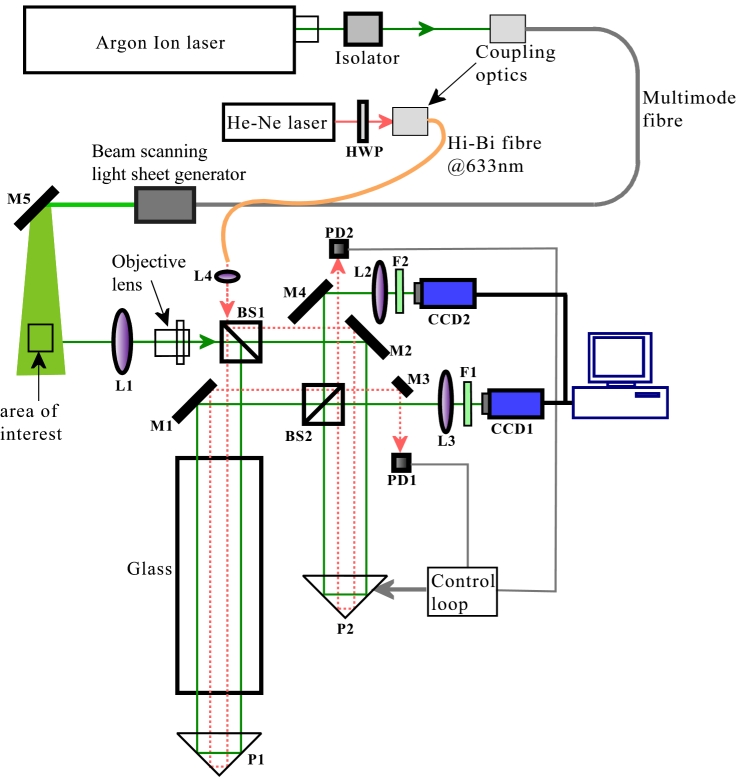
Figure 2 The experimental arrangement of the complete single velocity component measurement Mach-Zehnder interferometric filter based PDV system: HWP: half-wave plate; BS1, BS2: non-polarization sensitive beam splitters; L1: standard camera lens; L2, 3: tube lenses; L4: coupling lens; M1, 2, 3, 4, 5: mirrors; F1, 2: green filters; P1, 2: right angle prisms.
Results
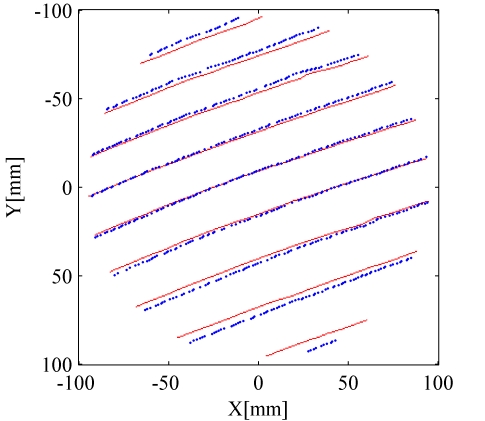
Figure 3 Skeletonised fringe positions showing the locations with the disc stationary (red) and moving (blue).
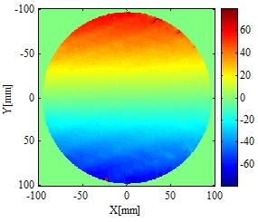
Figure 4 Computed velocity component of the rotating disc calculated using the normalised intensity method.
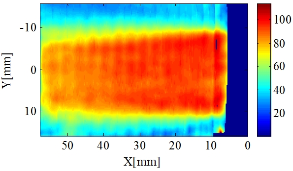
Figure 5 The computed main flow velocity of an axis-symmetric air jet with an exit velocity ~100m/s.
References
Mach-Zehnder interferometric filter based planar Doppler velocimetry (MZI-PDV)
Z-H Lu, T O H Charrett, H D Ford and R P Tatam
Journal of Optics A: Pure and Applied Optics 9, 1002-1013 (2007)
Interferometric filter based planar Doppler Velocimetry
Z Lu
PhD thesis, School of Engineering, Cranfield University, 2008