
previous next
Front cover of MST
The March 2012 edition of Measurement Science and Technology featured our review of optical fibre laser velocimetry and featured on the front cover (below). The cover image features fibre-optic imaging bundles coupled to borescopes to make planar Doppler velocimetry measurements within a gas turbine compressor.

Front cover of March 2012 edition of Measurement Science and Technology featuring the review paper on optical fibre laser velocimetry.
- Optical fibre laser velocimetry: a review (invited review paper)
T O H Charrett, S W James, and R P Tatam
Measurement Science and Technology 23, 032001 (32pp) (2012)
An inside-out snowman
21st December 2012 (by Jane)
I made an inside-out snowman from two integrating spheres. Below is a picture and line drawing to show the insides. This is also a personal tribute to the work of Rachel Whiteread, who amongst other things produced an inside-out house, and a library as a memorial to the victims of the holocaust.
The snowman’s body is made from two integrating spheres joined at two open ports. The arms are tubes that we use to pass gas into and out of the larger cell. The hat is made of pieces of SpectralonTM (see below) and the scarf is an electrical cable that I found in the lab.
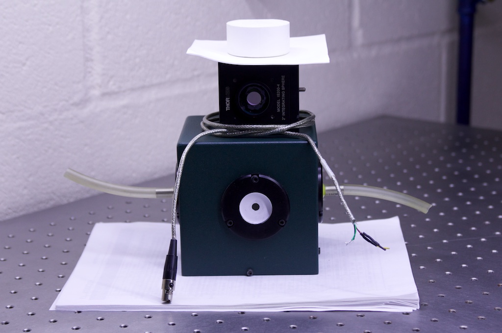
Photo of the inside-out snowman. The integrating spheres each have a spherical cavity within the cuboid.
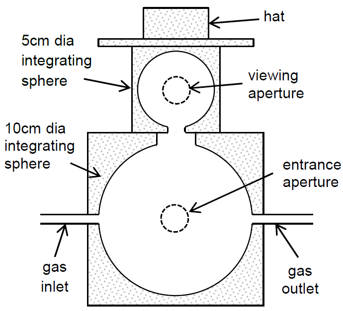
Schematic diagram of the inside out snowman made from two connected integrating spheres.
These devices are made from SpectralonTM, which is has a very high (~99%) diffuse reflectivity. When this material is wrapped around on itself to form a cavity, any light entering the cavity is able to bounce back and forth randomly, many times, until it is absorbed by the sidewalls, the gas we want to analyse, or a photodetector. For an ideal diffuse scatterer or Lambertian surface, the radiance L (in W m‑2 sr‑1) from a given point is a constant in any direction. For a cavity with spherical geometry, it follows that the irradiance at the surface E (in W m‑2) received from that point is then constant over the entire sphere[1][2]. Therefore, after only a few passes across the cell to remove the local effects of launch geometry, the irradiance is perfectly uniform over the surface, and a detector placed at the surface is able to make a representative sample of the irradiance everywhere else. This makes integrating spheres ideal for use in measurement of parameters such as the total emission from light sources.
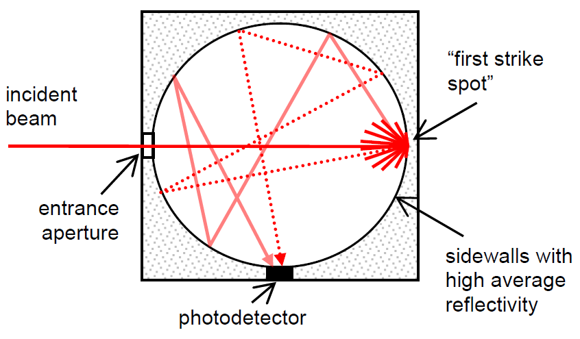
How light behaves in an integrating sphere, showing two examples of random light paths from laser to photodetector. In fact there is an infinite number of potential light paths.
To prove that the snowman works properly as an integrating sphere (or rather, integrating snowman), we performed the following experiment. Here, a laser pointer is being aimed into the lower integrating sphere port. When the beam enters the cell, you can see the port in the upper integrating sphere glow red.
When the light enters the lower sphere of the snowman, you can see a red glow in the viewing aperture of the top sphere.
We have been using integrating spheres in our gas detection work, as they provide a convenient multipass cell, increasing the light’s interaction length with the gas and improving our signal to noise ratios. Compared to other multipass gas cells, they are also spectacularly easy to align. Although they have been used in this context before, we have been unpicking the science behind this application. We worked out the nonlinearity in system response that results from the fact that there is no single optical pathlength within the cell[3][4] (it has a surprisingly simple analytical answer) and investigated the limit in performance caused by laser speckle in the sphere[5].
References
[1] Labsphere Inc. A guide to integrating sphere theory and applications. Labsphere, North Sutton, NH, USA, 1998.
[2] P Elterman. Integrating cavity spectroscopy. Applied Optics 9 (9), 2140‑2142, 1970.
[3] J Hodgkinson, D Masiyano and R P Tatam. Using integrating spheres as absorption cells: pathlength distribution and application of Beer’s Law. Applied Optics 48 (30), 5748-5758, 2009.
[4] J Hodgkinson, D Masiyano and R P Tatam. Using integrating spheres with wavelength modulation spectroscopy: effect of pathlength distribution on 2nd harmonic signals. Applied Physics B 2012, DOI 10.1007/s00340-012-5166-7
[5] D Masiyano, J Hodgkinson and R P Tatam. Gas cells for tunable diode laser absorption spectroscopy employing optical diffusers. Part 2: Integrating spheres. Applied Physics B 100 (2), 303-312, 2010.
Snowtonics: the photonics of snow?
20th December 2012 (by Jane)
Fresh snow is bright, white and opaque. What does this actually mean, optically?
Fresh snow is opaque
If you’ve seen snow, you will know this to be true. But why? Snow is made of, erm, snowflakes, which are made of ice, which is transparent, not opaque. Snow is what we call a multiple scatterer, in other words, most of the light that falls onto it is scattered around (inside the snow) several times before it gets out. The consequence of this is that light falling on the snow gets mixed up, randomised, and any information within it is scrambled. So, why you might be able to see distorted images through a clear block of ice, snow looks opaque white, just like a piece of paper, or the paint on your wall.
Why does this scattering occur? The refractive index of ice is about 1.31 and that of air is about 1. Any light beams hitting the interface between ice / air will be bent as a result of refraction (Snell’s Law) or reflection (Fresnel reflections or total internal reflection), depending on the angle of incidence. Do this a number of times to a beam of light and it undergoes a random walk within the bulk of the snow. Therefore snow is also a bulk scatterer.
Fresh snow is bright white
The reflectivity of snow changes little as a function of wavelength across the entire visible range. This has been shown for real snow by many studies including a highly cited piece of work by Teruo Aoki et al[1]. They used an optical fibre based light collector mounted on a tripod, and measured the collected light with a spectrometer, over real snow in 4 campaigns during February 1998 in Hokkaido, Japan. To ensure accuracy they compared their results to a diffuse reflectance standard made of SpectralonTM (for more see below). Their work also shows that the albedo (mean diffuse reflectivity) was around 90% across the visible region. In other words, highly reflective and with no colour – both bright and white.
Note that I said “fresh snow”. We all know that as snow gets older, it gets dirtier – basically, stuff lands on it. This reduces the albedo because a lot of the “stuff” is dark and absorbs the light.
How far does the light penetrate?
There’s no snow here right now so we’ll have to make do with some “ideal snow”, namely a piece of SpectralonTM (mentioned above for its use as a reflectance standard). In this photo I aimed a laser pointer at a slab of Spectralon and took a photo from the side. You can see that the beam has penetrated into the material by over 10mm. Note that SpectralonTM has a finer grain structure than snow does, and potentially lower absorption, but the same principles should apply.

When light from the laser pointer hits the side of the Spectralon block, photons travel over 10mm into the material. Some of them leave the top surface, enter the camera, and show up as red on this image
The amount by which light penetrates into real snow depends an awful lot on its microstructure (different sized ice grains [1]) and can vary with the snow conditions, the snow’s age, and how wet it is (wetness between grains significantly reduces the refractive index change as the refractive index of water is around 1.33 – close to snow’s 1.31).This material has a diffuse reflectance of approximately 99%, one of the highest known. How does it achieve this? We can think about what happens to the photons entering the material. If the material was infinitely thick, they could bounce around a bit until they leave from the surface they entered, they could be absorbed by the material or by impurities, or they could … er … bounce around a bit more. So as long as there is lots of scattering and not very much absorption, the diffuse reflectivity will be very high. The consequence of this is that in order to achieve high reflectivity the material must be quite thick (the manufacturers say at least 10mm), or else the light will leave the far side, never to be seen again. And it must have a suitable microstructure with lots of refractive index changes, with very low levels of light absorption.
If we get any new snow in the near future, I’ll try and repeat the laser pointer experiment. Or get one and try it yourself! It works best in the dark.
Snowtonics and The-Future-of-Civilisation-As-We-Know-It
The reflectivity of snow is an important factor in the Earth’s energy balance[2] – more snow means more reflected sunlight and less global warming. And vice versa – as the planet warms and snow melts, more sunlight is absorbed and the planet warms further, which is why melting snow provides the potential for positive feedback to global warming. Understanding the amount of snow and the level of reflectivity it offers are important elements of the global climate models used to inform environmental policy and reports by the IPCC (Intergovernmental Panel on Climate Change). For example, scientists studying the Greenland ice sheet recorded record levels of ice melt during 2012 [3];
“The lowest surface albedo observed in 13 years of satellite observations (2000-2012) was a consequence of a persistent and compounding feedback of enhanced surface melting and below normal summer snowfall.”
Using diffusely reflective materials in our work
We have used diffusely reflective materials like the SpectralonTM above in our gas detection work. The gas cells we designed are easier to align than traditional cells, which should make them more field robust [4]. One of the key considerations for our research was to understand the resulting laser speckle from materials like Spectralon and to minimise the noise that it adds to our data [5]. An image of laser speckle from SpectralonTM is shown below.
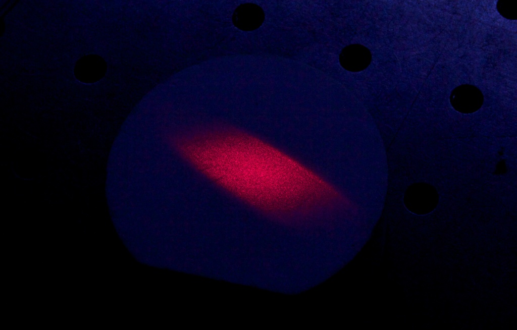
Image of laser speckle in an expanded beam from a laser pointer
I think of this as “fuzzy optics”, by analogy with fuzzy logic.
Other groups working on this approach include Siemens in Munich, who developed an oxygen monitor for use in industrial boiler flues [6], and a group at Lund University who have measured gases from within various scattering media including biological tissue [7], pharmaceutical pills [8] and engineered ceramics [9].
You can try the laser speckle experiment yourself with a laser pointer and a piece of paper (in the dark). The sparkly bits are laser speckle. Now bend your forefinger round to make a small hole and place this in front of your eye while looking at the speckle. As you make the hole smaller, the speckles should get bigger. This proves that laser speckle size is a property of the viewing aperture and not the reflective material. If you want to take a photo, aim to use your camera with its lowest NA (highest F/#). In the image above, we used an aperture of f22.
Finally, I used these materials to make an inside-out snowman – more tomorrow!
References
[1] T Aoki, T Aoki, M Fukabori, A Hachikubo, Y Tachibana and F Nishio. Effects of snow physical parameters on spectral albedo and bidirectional reflectance of snow surface. Journal of Geophysical Research 105 (D8), 10,219-10,236, 2000.
[2] AJ Dietz, C Kuenzer, U Gessner and S Dech. Remote sensing of snow – a review of available methods. International Journal of Remote Sensing 33 (13), 4094–4134, 2012.
[3] JE Box, J Cappelen, C Chen, D Decker, X Fettweis, E Hanna, NT Knudsen, T Mote, K Steffen, M Tedesco, RSW van de Wal and J Wahr. Greenland Ice Sheet. Artic Report Card: Update for 2012. November 28, 2012. Available at http://www.arctic.noaa.gov/reportcard/greenland_ice_sheet.html.
[4] J Hodgkinson, D Masiyano and R P Tatam. Gas cells for tunable diode laser absorption spectroscopy employing optical diffusers. Part 1: Single and dual pass cells. Applied Physics B 100 (2), 291-302, 2010.
[5] D Masiyano, J Hodgkinson and R P Tatam. Use of diffuse reflections in tunable diode laser absorption spectroscopy: implications of laser speckle for gas absorption measurements. Applied Physics B 90, 279-288, 2008.
[6] J Chen, A Hangauer, R Strzoda and M-C Amann. Laser spectroscopic oxygen sensor using diffuse reflector based optical cell and advanced signal processing. Applied Physics B 100 (2), 417-425, 2010.
[7] M Lewander, ZG Guan, K Svanberg, S Svanberg and T Svensson. Clinical system for non-invasive in situ monitoring of gases in the human paranasal sinuses. Optics Express 17 (13), 10849-10863, 2009.
[8] T Svensson, M Andersson, L Rippe, S Svanberg, S Andersson-Engels, J Johansson and S Folestad. VCSEL-based oxygen spectroscopy for structural analysis of pharmaceutical solids. Applied Physics B 90 (2), 345-354, 2008.
[9] T Svensson, E Adolfsson, M Lewander, CT Xu and S Svanberg. Disordered, Strongly Scattering Porous Materials as Miniature Multipass Gas Cells. Physical Review Letters 107 (14), 143901, 2011.
A Photonicly perfect Christmas tree
19th December 2012 (by Matthew Partridge)
This week is our last week of work before breaking for the Christmas/New year holiday. As it’s the last week, the office has taken on a decidedly festive air (someone had a christmas card on their desk) and I was thinking how we could make our work more seasonally appropriate. So after some group brain storming we decided that we can help everyone out this Christmas by calculating the best possible arrangement of christmas tree lights 🙂 I have written up the math in this post as a python script for anyone wanting to double check it.
Through extensive research, I have found that people <3 lights, therefore I assume that the best arrangement is the most possible lights. So what I think is the best place to start is to calculate the optimal viewable density of christmas tree lights. What I mean by viewable is; if you are standing say 10 m away from the tree what density of lights can you have before they all just blend into one big glow. I chose 10 m as this is average width of a street (UK) and I assume that part of the point of a christmas tree is that your neighbours can see how much better it is than theirs.

Project aim: make people walking past your house super jealous
With a little googling I discovered that people with 20/20 vision can resolve objects 1 arc minute apart. What is 1 arc minute I hear you ask, well it’s complicated but basically it’s 1/60 of a degree in your field of view. So if you had two objects on a table and drew an imaginary triangle (the best kind) between you and the two objects, providing your viewing angle is greater than 1/60 of a degree, your eye can resolve the difference between them. Simple.
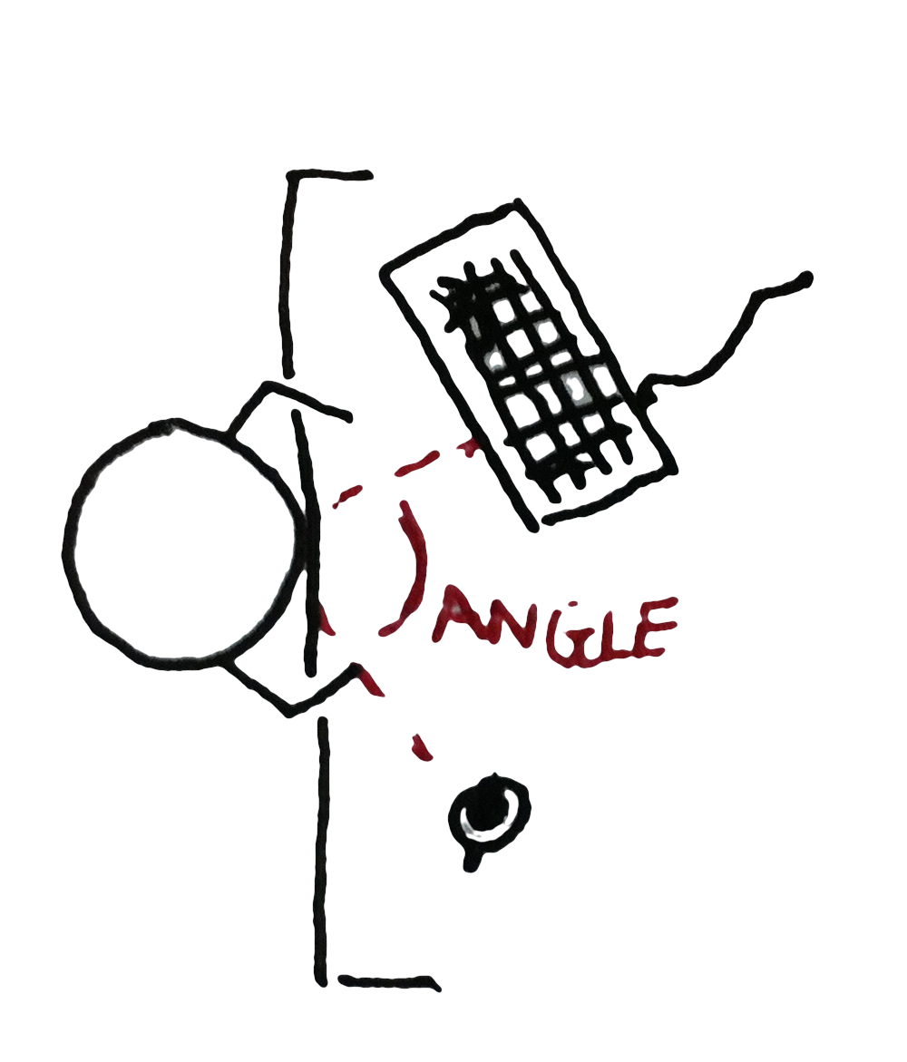
Viewing angle between two objects in your field of vision
So with a little trigonometry we can calculate that from 10 m a christmas tree with the hight 1.8 m (seems like a pretty average tree) from top to bottom is around 40 degrees which is equivalent to 1239 arc minutes. If you then do the same for the width, assuming the tree is 1 m wide which gives you a further value of 687 arc minutes. Multiplying these two together will then give us the number of resolvable points available on the tree: 85,1193. Pedants might point out that trees are rarely exactly 1.8 x 1 m square and come in many different shapes, to which my reply is “shut up, this is difficult enough”.

See simple!
If we feed the number of visible points back into the measurements of the perfectly rectangular tree we can calculate that there are 47 viewable points every cm2; therefore if you covered your tree in lights at this density they would still look like nice twinkly individual lights. Job done, yet another triumph for practical science.
[ED: err 85,1193 lights doesn’t sound very practical, care to try again?]
No, and anyway it’s 1,702,386 lights, the tree has two sides. I suppose I could meet you half way and run the numbers on powering up this awesome spectacle.
Assuming that firstly you have found some lights that you can pack at a density of 47 per cm2; and secondly that you have found a tree capable of supporting their weight, one thing I assume you’ll want to know is what electricity bill you might expect. There are two routes you can choose here, LED or Mini-bulbs. Mini-bulbs (~0.5 watts per light) are still more common and are essentially little incandescent lights, if you run the numbers these will draw around 0.8 Mega Watts which is around 90% of the output of the UKs largest solar energy park. If you are a bit more environmentally conscious then you might opt for LED lights (~0.07 watts per light) which work out far more efficient and only use 0.1 mega watts. If you then work this out in terms of actual cost (based on average UK prices) you can have your tree on 5 hours a day for the very reasonable sum of £70/day, not including the initial cost of installing specialist cabling to handle the power load. Considering you will have already spent around £140,000 on the lights in the first place this really seems like a bargain. Besides the cost of this will pale in comparison to the warm feeling you’ll get from looking at a tree that is around x1500 brighter than a laser pointer (assuming only 7% of the energy is converted to light), although it will very likely be the last thing you see.
The lights may be a little brighter than other trees, torches, car headlights, stadium lights or IMAX projectors you may have lying around.
[ED: Only 7% of the energy is converted to light…where’s the rest going?]
Well, you know that warm feeling I mentioned…? LEDs produce heat as well as light (around 75% of the energy, compared to 90% in mini-bulbs), and 1,702,386 lights produces a LOT of heat. Making the numbers for heat make any kind of sense is a bit tricky as there are several ways of measuring the heat output of any object. I think the easiest way is to work out what this heat might do to our poor christmas tree (i.e. how hot will the tree get). Using some basic chemistry math and assuming the tree is mostly water, the simplest way of explaining the heat generated is by calculating the increase in the temperature of the tree while the lights are on.
Worryingly people watching your tree burn seem quite pleased with the idea
If you work this out (assuming the tree weighs around 25kg) when with mini-bulbs, the temperature of your tree will increase by about 200℃ per minute while you have them on. As wood ignites at around 400℃ you’ll get a nice 2 minutes viewing followed by a nice evening round the bonfire that is where your house used to be. LEDs are a lot better and only raise the temperature of the tree by 26℃ per minute, meaning you get a nice 16 minutes to enjoy your display before running for your lives.
[ED: seriously, this is your idea of practical, burning houses?]
Fine, I suppose I could work the math backwards and work out what number of lights WON’T burn your house down. A quick estimate put this value at around 4.5 LEDs every cm2 (170,239 total), which is both practically achievable given the size of LEDs, and infinitely more boring. I think a better alternative is to stick to 47 LEDs per cm2 but set them up so that only 1/10 are on at any one time. That way you can have them twinkling nicely. If you replaced the tinsel (which is buried in lights anyway) with some kind of water cooling system then you might even be able to get this down to 1/5.
So I hope this has been a helpful little exercise in choosing how to decorate your festive tree. Once again I feel science has provided a clear and simple answer to a complex problem millions of people struggle with every year. MERRY CHRISTMAS.
Gas sensing review article
11th December 2012 (by Jane)
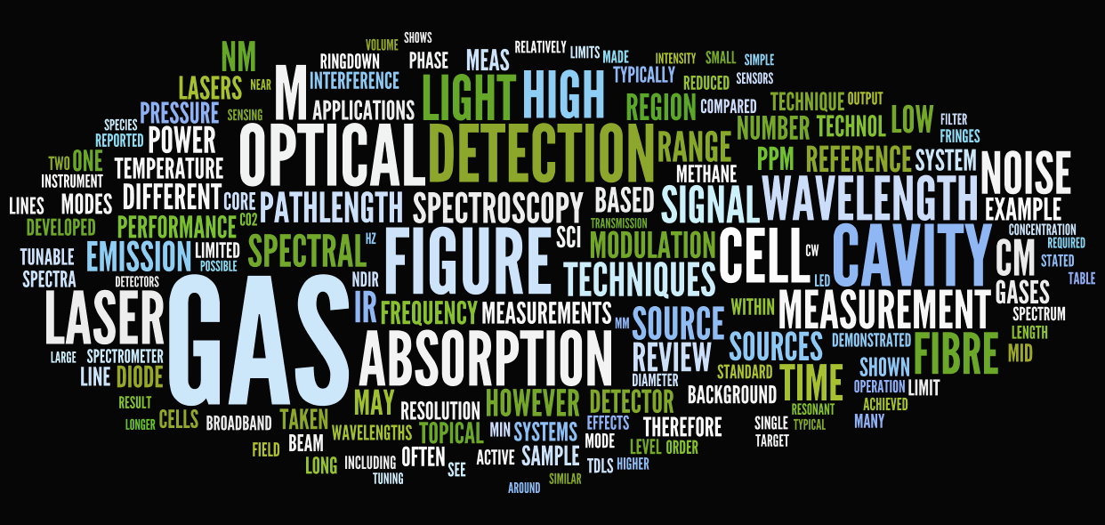
The review paper presented as a ‘wordle’
The review article I (Jane) put together with Ralph Tatam on optical gas sensing has just been published online by the journal Measurement Science and Technology. You may remember this review from my previous blog post on the problems with journal copyright.
Optical gas detection is a wide reaching field that impacts on industry, environmental study and safety. Given this importance the field moves rapidly with a large number of groups working with a diverse range of techniques. Our paper seeks to highlight the changes in this field over the last 10 years and provide a detailed analysis of their impact on the challenges in gas detection. The review is divided into several sections with particular focus on 6 key areas;
- Optical gas cells (e.g. multipass Herriott cells and integrating spheres)
- Non-dispersive sensors
- Spectrophotometry (including miniature spectrometers)
- Tunable diode laser spectroscopy (TDLS)
- Cavity enhanced techniques (cavity ringdown spectroscopy and cavity-enhanced absorption spectroscopy), which can be used with techniques 2-4 above.
- Photoacoustic detection, which can also be used with the above techniques.
In addition this review brings these techniques together in a comparison table, sub-divided into various gases of interest (ammonia, benzene, carbon dioxide, carbon monoxide, ethane, formaldehyde, hydrogen sulfide, methane, nitric oxide, nitrous oxide, nitrogen dioxide and sulfur dioxide).
We hope that this review paper is an ideal starting point for anyone wishing to get an overview of current trends and developments in optical gas detection. The article will be FREE TO DOWNLOAD until 29th December using this link.
The animated GIFs of Movember
7th December 2012 (by Matthew Partridge)
A little over a month ago I wrote about 5 members of our department and their pledge to grow a moustache for Movember. Movember, for those that missed the first post, is the awareness campaign for prostate and testicular cancer, where each person pledges their support by growing a moustache for 30 days. Well all 5 of them gave it a go (some were more successful than others) and below is the group photo showing their efforts.

L to R; John, Tanmay, Tom, Steve and Mark
At the start of Movember I also asked those taking part to have their photograph taken every day. The idea was to use the images to chart their moustache growing skills. This little sub-project had mixed success as some people (Tom) were not very good at remembering to come by for a photo everyday – it’s almost like they were busy doing actual work! But I did manage to get enough photos to make a series of animated GIFs for each of the 5 intrepid growers.


————-
 ————-
————-
In order to make these, I had to spend 2 hours staring at these pictures, lining them up correctly – I may never be the same again…
Finally, some members of the department felt left out – either by their inability to grow a moustache or because they started after the start of Movember. So to show their support of their colleagues’ itchy faces and the Movember campaign, they all got together for a display of solidarity.

L to R; Oliver (possibly evil twin), Fei, Jane, Helen, Rebecca and Sahar

There are far too many people to list, just check the other photos if you want to know their names!
The second group photo is, rather worryingly, the closest thing we have to a departmental photograph.
In the interest of balance I should point out that not everyone is a fan of the Movember campaign. Margaret McCartney wrote an excellent piece in the BMJ about both the campaign’s rather bad referencing (no NHS backed resources are even mentioned on the Movember site) and their promotion of testing regimes without scientific evidence. I don’t think it’s unreasonable to ask that any medical guidance is backed by multi source, high quality evidence and not soundbite advice put together after “we did consult with a medical expert….”. I still think Movember is a very worthy idea that helps get discussion about men’s health more widely accepted, but I agree with Dr McCartney that this publicity and discussion is worthless if the advice and guidance being offered is rubbish.
Remember, remember the 1st of movember
1st November 2012
This is just a short post to let you all know that some of the department are growing (or trying to grow) moustaches for Movember this year. This campaign is to raise awareness of prostate and testicular cancer. Wile these cancers are well known to most people, they are still two conditions that most men are very reluctant to talk about or even get checked for. In my previous job I worked on developing a rapid prostate cancer test and I got to know some of the charities involved in raising awareness. These charities worked tirelessly to promote testing and publicising the symptoms of prostate and testicular cancer. At one large free screening event (organised by Graham Fulford) I was helping with, a staggering proportion of the men that attended said they only came because their wives insisted! There is a real need to change the way men think about their health and campaigns such as Movember are crucial in reminding people that these are not diseases that can just be ignored.
Supporting this campaign are; John Davenport, Mark Manders, Tanmay Tipnis, Thomas Charrett and Steve James. Last year we also persuaded the head of the department to take part but his is currently away and no one is sure if he’s joining in. Below are their day one mug shots.

From top left to bottom right; John, Mark, Tanmay, Tom and Steve
I hope that over the 35 day Movember campaign we can manage to photograph them pretty much every day and produce some nice time lapse videos at the end of it. If you would like to support Movember you can donate here or you can donate directly to either of the charities I mentioned before at Prostaid.co.uk or through the just giving page for The Graham Fulford Charitable Trust.
OFS 22 Beijing, China
16th October 2012
Steve, Fei and Thomas are attending the international conference on optical fibre sensors (OFS) this this week and are presenting a number of poster presentations of their work. If you are attending please go see them, they are only too happy to talk to people interested in the odd things we do!
Poster Session 1: Tuesday 16th October 2012
PO1‐4 Multiplexing tapered optical fibres using coherent optical frequency domain reflectometry, Renata Jarzebinska, Edmon Chehura, Stephen W. James, Ralph P. Tatam, Cranfield Univ. (United Kingdom) [8421‐32]. Coherent optical frequency domain reflectometry is used to multiplex a serial array of tapered optical fibre sensors. By monitoring changes in the Rayleigh backscattered signal from tapered regions of a single mode optical fibre, the refractive index of the medium surrounding each taper can bedetermined. The approach is used to demonstrate a liquid flow sensor.
PO1‐43 Toward track component condition monitoring using optical fibre Bragg grating sensors, S. J. Buggy, S. W. James, S. Staines, Cranfield Univ. (United Kingdom); R. Carroll, Stagecoach Supertram (United Kingdom); P. Kitson, D. Farrington, L. Drewett, J. Jaiswal, Tata Steel RD&T (United Kingdom); R. P. Tatam, Cranfield Univ. (United Kingdom) [8421‐34]. Optical fibre Bragg grating sensors have been field‐trialed for the monitoring of dynamic loading of fish‐plates, stretcher bars and switchblades on a tram network, with the aim of developing a condition monitoring system. This paper provides preliminary data showing the ability to identify changes in track/component condition.
PO1‐109 A 1.65 um region external cavity laser diode using an InP gain chip and a fibre Bragg grating, F. Chen, J. Hodgkinson, S. Staines, S. James, R. Tatam, Cranfield Univ. (United Kingdom) [8421‐538] We present the construction of an external cavity laser (ECL) diode using an InP semiconductor gain chip and a fibre Bragg grating (FBG), designed to have an emission wavelength that coincides with an absorption line of methane, to be used for spectroscopic gas sensing. The FBG was employed as a wavelength selective and feedback element, which will potentially provide the laser with wavelength tuning capability. Narrow linewidth lasing output of less than 5 MHz was achieved. To our knowledge, this is the first FBG based ECL in the 1.65 μm region.
Poster Session 2: Wednesday 17th October 2012
PO2‐4 Optical coherence tomography for endoscopes, using imaging fibre bundles and a conical mirror, Helen D. Ford, Ralph P. Tatam, Cranfield Univ. (United Kingdom) [8421‐293] Imaging fibre bundles and a conical mirror have been used to construct a passive, endoscopic OCT probe with no scanning components at the probe tip. Circular scanning of the beam projected onto the proximal face of the imaging bundle results in a corresponding circular scan at the distal end of the probe. A 45o base‐angle conical mirror turns the output light to produce a radially‐directed beam that permits circumferential OCT scanning in quasi‐cylindrical ducts.
PO2‐107 Range‐resolved single‐sideband optical fibre interferometry for quasi‐distributed dynamic strain sensing, Thomas Kissinger, Thomas O. H. Charrett, Ralph P. Tatam, Cranfield Univ. (United Kingdom) [8421‐352] A novel optical signal processing scheme for fibre sensors is proposed, which combines interferometric phase measurements with range multiplexing. The scheme is based on single‐sideband signal processing and uses continuous‐wave pseudo‐random range encoding. The potential of the technique for cost‐effective dynamic quasi‐distributed strain sensing is explored by applying it to an array of fibre segments. In its current implementation dynamic strains in segments of 3.4 m gauge lengths can be measured with a resolution well below microstrains at a bandwidth of 100 kHz.
Poster Session 3: Thursday 18th October 2012
Journal copyright for figures – why it takes aaaaages
10th October 2012 (by Jane)
Some time ago now, in a weak moment, Ralph and I agreed to write a review article on optical gas sensing for the journal Measurement Science and Technology, an IoP journal. This is a huge field and to do it justice we have written a rather large article with over 400 citations and 60 figures. It has been through peer review and is reaching the final stages of preparation, one of which is to get copyright permission to reproduce images from other peoples’ publications. Standard practice is that the authors have to do this, ie me.
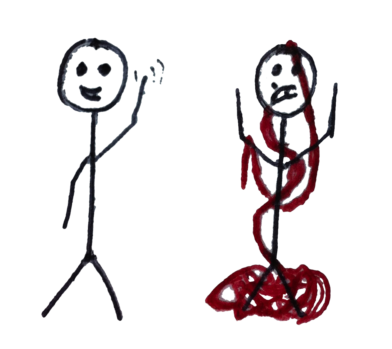
The difference red-tape laden copyright processes can make to a happy scientist
A review article is essentially a pointer to the latest work in the field, with the odd bit of comment and explanation. Illustrations help the reader, make the paper more interesting and are likely to attract greater interest than the text. This means readers might go on to cite the source article in their own work, increasing impact factors of the source journals etc.
So you might think it was an advantage to have your work in a review article. Well, somebody needs to tell this to the IEEE, who want to charge a fee of £45 for each figure. None of the other publishers I contacted wanted a fee – not even Nature!
Having nothing better to do with my time ;-), I looked for alternative images. For the first offending image I found the same picture, by the same author, in a journal by a different publisher (Elsevier). For the second I found a similar image from a different author, also published by Elsevier, which told the same story. So it’s in with Elsevier (and their membership to Rightslink), out with IEEE. Despite their recent poor publicity, this is something that I think Elsevier have got right.
My second problem is also a result of journal copyright policy. Generally, authors sign over the copyright in their work to the journal when their article is in press. One advantage of this (for me) is that I only have to contact the publisher, as the copyright holder. However, one organisation (SPIE) also required me to contact the authors directly for their permission as well. Let’s look at the consequences of this policy in my stats:
1. Optical Society of America (OSA). I used 10 figures all from different articles, sent one email and had one reply. Job done, and thank you very much.
2. SPIE, the International Society for Optics and Photonics (a rival organisation to OSA). I used 8 figures from different articles and have now sent 20 emails over a period of 5 weeks. As SPIE don’t routinely provide email addresses for the corresponding authors, I had to Google several authors and failing that phone their company receptionists to find them (international calls). In the end I redrew one of the images and SPIE have finally given permission where I have struggled to make contact with all the authors. Actually this process resulted in one organisation giving me new (and otherwise unpublished) data for the article, with their blessing.
What do you do then? Well, in order of easiness:
(i) Draw it yourself from scratch where you can.
(ii) Redraw any easy line drawings (they will look better that way anyway) – this is OK as long as you still cite them properly.
(iii) If your publisher (eg IoP) and the publisher of the cited article (eg Elsevier) are both STM signatories, you can rest easy: they have a reciprocal arrangement under STM guidelines and you don’t have to request permission.
(iv) Think twice about reproducing anything from journals with non-standard copyright policies if you value your money or your time.
Finally, a big thank-you to the authors I contacted who replied promptly and with grace, including the esteemed professor who I wrongly addressed as “Dr” (big oops) and the professor who sent me a better quality photo than the one I had cut and pasted from a pdf of his paper.
The article will be published in due course and you can see what’s in it then; by reading this you know why some of it is the way it is.
UPDATE: the article is now published.
Lab books exposed
5th October 2012 (by Matthew Partridge)
In academia and industry there is still a reluctance amongst many scientist to share the details of their work with the wider community. Science has a long history of publishing results in peer-reviewed academic journals. However, a growing number of researchers think that there is scope for wider openness and access to more detail of their published work. I will leave the reasons why I support this open-access model to another time as it is really part of a bigger discussion about improving the dissemination of science to related fields and to the public. Shifting from the old model to one based around openness and sharing is a very slow process and requires changes both to the way science is funded and to the attitudes of current scientific researchers. While we are working on new ways to acquire funding in order to run open-access projects, like our soon to be launched crowd funded project, we are also keen to demonstrate ways that researchers can show their commitment to open-access work.
I first came across #showusyourlabnotes via the Open Science federation and Tommy Leung and immediately loved the idea! As a mini-campaign it provides scientist with a way of showing their support for open-science through action rather than just simply agreeing that the principle is sound. So, after surprisingly litter persuasion, the entire department (bar a few people that aren’t in) has agreed to show off a random page of their lab-notes in support of open-science.
The lab books shown above (click to show more detail) cover a very wide range of work from optics lab work (Helen) to some pretty heavy algebra (Tom) and even some basic monolayer chemistry (Matthew). What we also hope this shows is that the work done in many fields of science is far from the neat and tidy experiments presented in journals and there is a wealth or techniques and data hidden away in lab books and notes.
N.B. As the department is currently funded by fairly traditional routes the majority of the work we do is protected by confidentiality agreements, so a few of the lab-books might be a little dated. It is a testament to the need for open-science that the fine detail of work that has already been published is still protected under confidentiality agreements!
Brewster angle Lego microscope
1st October 2012 (by Matthew Partridge)
Brewster’s angle is the angle at which light of a certain polarisation won’t reflect off a surface. The resulting reflection will then be made up of only light from a single polarisation (p-polarised). This little optical quirk is how polarised lenses remove lots of scattered reflections in photographs and why polarised sunglasses are so much better when lounging by the seaside. However, rather than just being something that makes sunny days even better, it also provides a neat trick for visualising things that would otherwise be invisible to other analytical methods.

‘Simple’ Brewster’s angle schematic
Brewster’s angle for water is approximately 53.1°, which is calculated from knowing the refractive index of the water and the surrounding air. If either one of these values was to change, then the angle would also change. For example, if your measured the Brewster’s angle of a film of olive oil (refractive index of ~1.46) you’d get around 55.7° which is quite a big shift (relative to most things in optics).
Now, if you set up a light source and camera at exactly 53.1° over a tank of water and block all the s-polarised light bouncing off the surface into the camera then all you will see is black. If you introduce to the water surface a contaminate, such as oil, this will change the Brewster’s angle and so the water will begin to reflect p-polarised light, which will pass straight through the s-polarised filter and into the camera. So, from the camera’s point of view, the water will appear black and the oil will appear bright. This will work no matter how thinly the material is spread, so if you have just a single molecule thick layer (~2 nm which is around the same thickness as a single strand of DNA) this will still show up nice and bright on the camera. (this is much clearer in the video but we’ll get to that in a moment).
Looking at materials like this provides a wealth of information to scientists on the way materials interact with each other or with the water beneath them. In the main this is used as a tool for examining materials for further use in applications such as benzene sensing or medical device coatings or examining a range of novel exotic materials. However it is not a commonly used technique, one reason for which is cost of a Brewster Angle Microscope (BAM). Recent developments in Micro-BAMs have brought the cost down but a BAM currently costs anything from £20,000 – £75,000, which is serious money. When I did this work I was a lowly PhD student with purchasing authority for the grand sum of £0, which is some way off £20,000, so I realised that if I wanted some nice pictures of my materials then I would need to get creative.
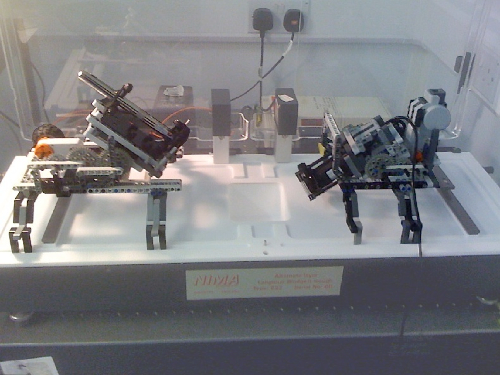
Lego BAM rig set up over a NIMA monolayer trough
The photograph above shows the second generation design of my home made BAM. The first design was made using laboratory retort stands which just about worked but the lack of gearing, motors or align-able parts meant it took a hour just to get a poor quality fuzzy image. The second generation has the major advantage of being made with Lego. A vital part of the BAM is getting the laser (1 mW green laser pen from SP3Plus Ltd) and the camera ( VMS-001 Veho, bought second hand) to align correctly. This was big problem in the hand-adjusted version because, not only were we trying to get the angle right, we were also trying to line up the the laser and the microscope. Lego neatly solved this problem by having such insanely high tolerances (~10 µm) on it’s parts, so I knew that if I build two identical frames and mounted the laser in the centre of one and the camera in the centre of the other they would aligned well enough to get a 0.5 mm beam into a 2.5 mm camera aperture. The frames shown also include motors and gearing to allow for simple changing of the angle of the camera or laser. These motors were re-calibrated at the start of every experiment so that specific changes could be made for an accurate measurement of the Brewster’s angle for the material being used. Attaching the laser and the camera to the frames was a little trickier as unfortunately neither Veoh or Sp3 make their respective kit with lego mounting or dimensions in mind. Conveniently, the Sp3 laser did come with a mounting rig which had mounting pins on the bottom plate, by chance these pins were within 0.5 mm of the required positions to simply drop them in to lego frame, this was quickly rectified with some sand paper. The camera however didn’t come with anything and was mounted using a V-shpaed holder this ensured that the centre of the camera lined up with the laser and it also allowed for an additional mount for a polarising lens to cover the camera aperture. More photographs of the finished system can be found here and here.
Finally once it was all set up the system was tested with some stearic acid (a common fatty acid) and it produced the video shown below.
http://www.youtube.com/watch?v=3sRo2OKbT90
As I mentioned before, the white shapes in this video are the stearic acid material floating on the black background. The shapes shown will naturally move around in the air currents in the lab and any residual currents in the water the material is spread on. The material spread in this video has been prepared in such a way that the film shown is only 1 molecule thick. In some regions it may be more than this and these show up brighter than the majority of the film.
The microscope is currently undergoing a re-design and I hope that the 3rd generation will produce even clear images (auto focusing) over a wider area. I am also quietly optimistic that I can also motorise the polarising lenses, which would allow me to collect much more data on each material. Once improved I’ll publish a follow up set of results here. In the mean time you can always follow me on twitter (@MCeeP) to get some more detail on this and other work we do.
Latest publication in Sensors and Actuators B
1st October 2012
Our latest paper, published in Sensors and Actuators B, describes a highly sensitive device for detecting and quantifying the concentration of carboxylic acid. The work is part of an on-going collaboration between the Department of Engineering Photonics at Cranfield University and The Graduate School of Environmental Engineering at the University of Kitakyushu, Japan, exploiting optical fibre based sensing platforms developed at Cranfield with the novel functional materials and coating techniques investigated by Prof Lee’s group at Kitakyushu.
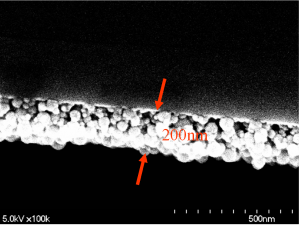
Optical fibre with mesoporous coating of SiO2 nanospheres
The operation of the sensor is based on the measurement of the change in refractive index of a functional coating deposited onto the cladding of the optical fibre. Mesoporous thin films were fabricated using the layer-by-layer self-assembly of poly(allylamine hydrochloride) (PAH) and silica nanospheres (SiO2) with a diameter in the range of 40–50 nm. The amino (NH2) functional group of PAH was used as the binding site for the detection of ACAs. High sensitivity to benzoic acid and mellitic acid, respectively, was observed. The lowest measured concentration of 1 nM of mellitic acid was detected selectively over structurally(phenol) and functionally (acetic acid) related compounds.
Full Citation:
Pronounced aromatic carboxylic acid detection using a layer-by-layer mesoporous coating on optical fibre long period grating
S Korposh*, T Wang*, S W James, R P Tatam, and S-W Lee*
Sensors and Actuators B (2012).
As always, a full list of publications from the Department of Engineering Photonics is available here.
EWOFS 2013 Announced
24th September 2012
The 5th European Workshop on Optical Fibre Sensors (EWOFS’2013) will be held in Krakow, Poland form the 19th to 22nd May 2013.
EWOFS has a different format to many conferences. Each session begins with keynote presentations from leading figures in the filed. These are followed by a poster session themed in line with the keynote presentation. The aspect that differentiates this conference comes next. Attendees are allocated to a discussion group, facilitated by a member of the technical program committee. The discussion groups meet after each poster session to talk about the posters – typical discussions might identify new and emerging trends, comment on the papers that make the most significant contributions. The facilitator is then tasked with trying to pull the threads of the conversation together to make a coherent story that is fed back to the conference.
If the idea of discussion groups fills you with dread, then don’t let it put you off. It is a great opportunity to share your thoughts with the big names in the field, as they are distributed amongst the discussion groups. At the last EWOFS, in Porto, I was facilitated a discussion group that, among others, had Robert Liebermann and Raman Kashyap as members.
Important Dates:
- 24th February 2013 – Paper submission deadline
(4-page camera ready paper) - 10th March 2013 – Author notification
Paper published in Thin Solid Films
24th September 2012
Jane Hodgkinson’s latest study on the use of integrating spheres in wavelength modulation spectroscopy has appeared on Applied Physics B‘s “online first service”
The detection and quantification of gas concentrations by measurement of their optical absorption has considerable great scientific and commercial importance. Extending the optical pathlength in gas sample cells is of interest to improve the signal to noise ratio (SNR) of this technique. Integrating spheres have great promise as multipass gas cells that require minimal optical alignment. However, the exponential distribution of optical pathlengths might be expected to influence the measurement.

Simple diagram of an integrating sphere
In the paper it was found that the gas lineshape becomes distorted at high concentrations, as a consequence of the exponential path-length distribution of the sphere, introducing nonlinearity beyond that expected from the Beer–Lambert law. The effect was for numerically methane absorption at 1.651 μm, with gas concentrations in the range of 0–2.5 %vol in air. The results of this model compared well with experimental measurements. It was shown that if this effect were not accounted for, the resulting error would be approximately 20 % of the reading at a concentration of 2.5 %vol methane.
Citation
Using integrating spheres with wavelength modulation spectroscopy: effect of pathlength distribution on 2nd harmonic signals
J Hodgkinson, D Masiyano and R P Tatam
Applied Physics B, (2012).
As always, a full list of publications from the Department of Engineering Photonics is available here.
Paper published in Thin Solid Films
19th September 2012
The latest output from the collaboration between us physicists and those chemist in Cranfield Health has appeared in print in the journal Thin Solid Films. The best bits of the paper are summarised below.

A comparison of a calix[4]resorcinarene monolayer with (bottom) and without (top) surfactant
This paper explores the properties of a number of calix-4-resorcinarenes along with their complexes with tetraalkylammonium surfactants and their behavior in Langmuir monolayers. The main findings are:
- anionic resorcinarenes and cationic surfactants form stable composite Langmuir films.
- Undecyl substituted resorcinarenes form more compact films than phenyl substituted.
- Both components of the composite are located at the air–water interface.
- Monolayers show side-by-side rather than head to head orientation of the counterions.
Full citation:
Monolayer behavior of calix-4-resorcinarenes and their surfactant complexes
Thin Solid Films, Volume 520, Issue 23, 30 September 2012, Pages 6989-6993
Matthew Partridge, Frank Davis, Steve W. James, Ralph P. Tatam, Charl F.J. Faul, Séamus P.J. Higson
As always, a full list of publications from the Department of Engineering Photonics is available here.
We have a blog!
18th September 2012 (by Matthew Partridge)
Hi, this post serves to explain a little about our motivations for having a blog and what we what to achieve with it. This blog represents a semi-offical attempt by our team (department of engineering photonics at cranfield university) to reach out to a wider audience. This was inspired by the fantastic STEM ambassador program (of which I and many of the group are members) which encourages professionals to explore ways of communicating science to schools. While initially the blog will be more focused at general public and professional engagement, we do hope that this will act as a platform from which to launch other wider reaching open access projects. At the very least we hope that for readers of the blog we can provide a new insight into the way research works and give you the opportunity to give feedback on how we can better communicate our work. (Translation: we hope it will be interesting enough to read occasionally).
More details on our current open research project can be found in the ‘Crowdsourced research project’ tab at the top of the page. We are still trying to bring a whole host things together to make it work, so details might be a little light at the moment. We will try and update you on it as much as possible as the project moves forward. In the meantime please read through some of our work and let us know what you think of our blog and our work.