
The concept of the PDV technique is very simple. Light scattered by particles seeded in the flow is Doppler shifted in frequency. The magnitude of the shift is dependent on both the propagating direction of the laser and the viewing of the region under investigation. The velocity of the particle is associated to the Doppler shift in the frequency of the laser light by the Doppler formula
$$!\Delta\nu=\frac{{\nu}_{0}\left(\hat{o}-\hat{i}\right)\cdot V}{c}$$
Where, $${\nu}_{0}$$ is the frequency of the laser, $$\Delta\nu$$ is the Doppler shift, c is the speed of light, V is the velocity of the particle, ô and î are unit vectors giving the observation and illumination directions respectively. Multiple components of the flow velocity can be measured by using either multiple observation directions or multiple illumination directions.
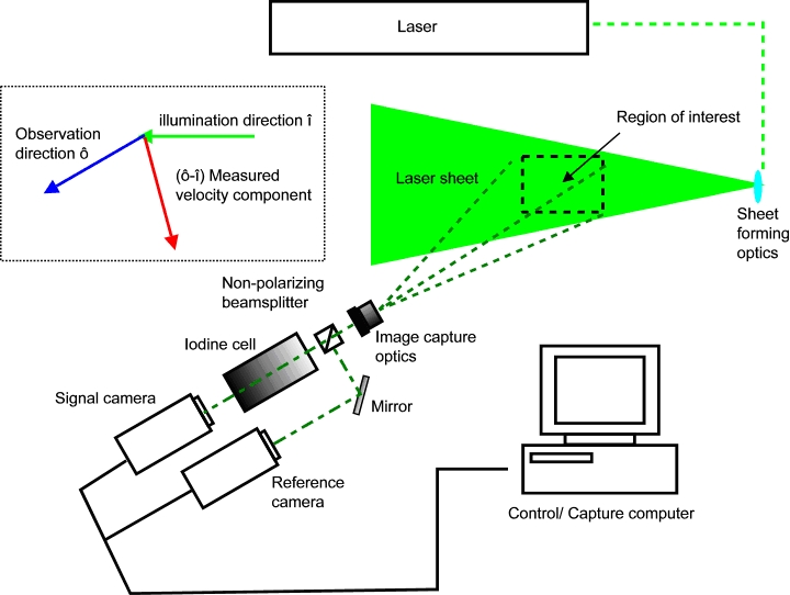
Figure 1 Schematic of a typical PDV system
A schematic of a typical PDV system is shown in Figure 1. Here the laser illumination is formed into a light sheet which illuminates a portion of the flow. Seed particles present in the flow scatter light which is Doppler shifted and is collected using a CCD (Charge-coupled device) camera.
(a) (b)
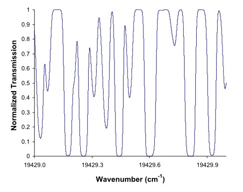
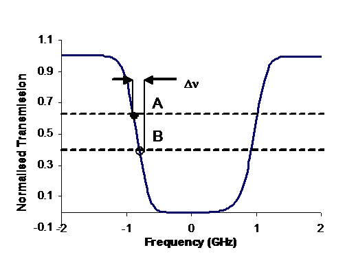
Figure 2 Iodine absorption lines around 514.5 nm (a). Concept of PDV using an absorption line as a frequency-to-intensity transducer (b).
To measure this Doppler shift and hence the velocity a frequency-to-intensity filter is used. In PDV this is a molecular filter – a glass cell usually containing Iodine vapour. Iodine has numerous narrow absorption lines over a large part of the visible spectrum (Figure 2(a)) and by tuning the illumination laser frequency ($${\nu}_{0}$$) to coincide with one such line, any frequency shift will result in a change in the transmission through the cell (Figure 2(b)). Hence the optical intensity at any position in the camera image is a function of the Doppler shift experienced at the corresponding position in the flow.
The intensity over a PDV image is also affected by other factors, the intensity profile of the illuminating laser sheet (typically Gaussian), spatial variations of the seeding density within the flow, and diffraction fringes caused by imperfections in the optical surfaces will all cause variations in the image intensity. These variations are generally of similar amplitude to those resulting from absorption in the iodine cell, and can obscure the information about flow velocity. It is therefore usual to amplitude-divide the image onto two cameras; one views the flow through the filter and records a signal image containing the velocity information. The other views the flow unfiltered and is used to provide a reference image with which to normalize the signal.
The laser used to illuminate the flow needs to be single mode and have a narrow linewidth and be matched to a suitable molecular filter absorption line. Typically either single-mode continuous-wave (CW) Argon ion lasers or pulsed injection seeded Nd:YAG lasers are used together with Iodine cells.
By using a CW laser such as an Argon ion laser time-averaged velocity measurements can be made. The higher power pulsed Nd:YAG lasers can be used to make instantaneous velocity measurements, effectively freezing the flow at the moment of the laser pulse.
Next: 3D velocity measurements