
3D velocity measurements using imaging fibre bundles
3D velocity measurements
Using a single observation direction can measure a single component of velocity given by the vector (ô – î). Therefore to measure multiple components of the velocity requires multiple observation, or illumination directions.
Single observation direction – multiple light sheets – Multiple velocity components are measured by sequentially illuminating the flow from different directions are recording images from a single observation direction. This has the advantage of requiring only a single PDV imaging head which usually views the light sheet orthogonally. However as the three components are now measured sequentially only time-averaged measurements are possible.
Multiple observation directions – single light sheet – Using a single light sheet which is imaged from three different directions allows all three components of the velocity to be measured simultaneously. However three PDV imaging heads are now required, each containing two CCD cameras and iodine cell. This is prohibitively expensive and complex.
Multiple observation directions using imaging fibre bundles – The use of imaging fibre bundles, pioneered at Cranfield University, to port multiple views of the region of interest to a single detector head, considerably simplifies a 3d-PDV system and makes it possible to make three component velocity measurements using a single PDV imaging head. This approach has since been adopted by some of the major research groups involved in PDV (Nasa, DLR).
Imaging fibre bundles
The imaging fibre bundles in use at Cranfield consist of a coherent array of fibres that is spilt into four channels (Figure 1(a)). These bundles have also been used for quantitative surface strain measurement in multi-component shearography. Each channel is 4m long, and has 600×500 fibres that are 8µm in diameter and positioned at 10µm centres. These views are combined at the detector head, with each occupying a quarter of the CCD image (Figure 1(b)).
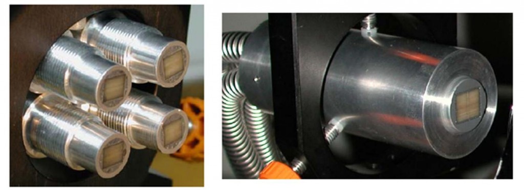
(a) (b)
Figure 1 The individual arms of the imaging fibre bundles (a) and the combined end of the imaging fibre bundles (b).
An example of the image formed is shown in Figure 2(a). This is a view of a calibration target used to de-warp the image to a common view and determine the observation directions for each view. Figure 2(b) shows the result after this de-warping process; here all four views have been overlaid for demonstration purposes.
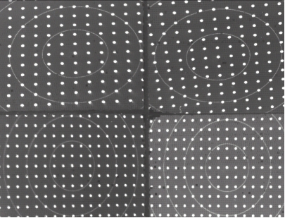
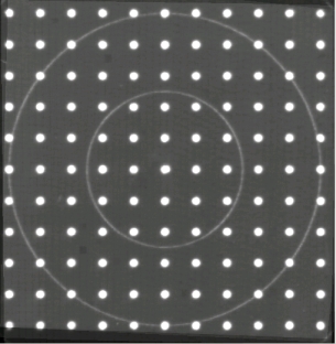
(a) (b)
Figure 2 An example image of a view through the imaging bundles of a calibration target (field of view ~100 x 100 mm) (a) and an example of the ‘de-warped’ views, showing all four views overlaid (b).
As well as providing flexibility in the location of the views, the use of fibre bundles allows different imaging optics to be used, for example SLR camera lenses for external flow measurement or borescopes for internal flow measurement (Figure 5).
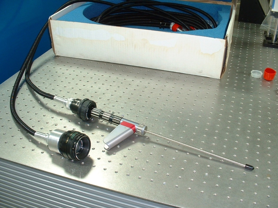
Figure 3 Imaging fibre bundles coupled to SLR lens and borescope (for internal flow measurement).
References
Single camera three component planar velocity measurements using two frequency planar Doppler velocimetry
T O H Charrett and R P Tatam
Measurement Science and Technology, 17, 1194-1206 (2006) (Special Issue from OFS-17)
CERES: https://dspace.lib.cranfield.ac.uk/handle/1826/5464
Three component planar Doppler velocimetry using imaging fibre bundles
D S Nobes, H D Ford, and R P Tatam
Experiments in fluids 36, 3-10, 2004
CERES: https://dspace.lib.cranfield.ac.uk/handle/1826/1129
Instantaneous, two-camera, three dimensional planar Doppler velocimetry using imaging fibre bundles
D S Nobes, H D Ford, and R P Tatam
Presented at the SPIE conference Optical Diagnostics for Fluids, Solids, and Combustion, San Diego, USA, 2001. Proc.SPIE 4448, 283-294, 2001