
Principle of Shearography and ESPI
Introduction
Speckle metrology encompasses a range of techniques that are used for non-contact, full-field inspection of diffusely reflecting surfaces. These techniques are used to measure a variety of properties including displacement, shape and surface strain, and are becoming increasingly important for material analysis, for example, in the aerospace and automotive industries. Speckle techniques rely on the illumination of region of interest on a diffuse surface with an expanded laser beam to produce a speckle pattern. A speckle pattern, such as that shown in figure 1, is formed by the coherent sum of interference of light scattered from all points within the illuminated region.
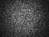
Figure 1 A typical speckle pattern formed by coherent illumination of a diffuse surface.
ESPI and Shearography
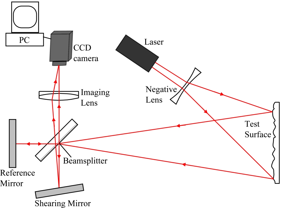
The principal speckle interferometry techniques are ESPI (electronic speckle pattern interferometry) and shearography. Schematic illustrations of typical optical arrangements for the two techniques are shown in figure 2. In ESPI, laser light is divided into illumination and reference beams by a beamsplitter. The illumination beam is expanded to illuminate the surface of interest and the scattered light is recombined with the reference beam to form an interferometric speckle pattern which is imaged onto the CCD camera. Speckle patterns recorded before and after object deformation are correlated by means of digital subtraction and the resulting image is a fringe pattern where the fringes represent regions of equal surface displacement. In shearography, the interferometric speckle pattern is created by combination of identical, but displaced (sheared) speckle images. The image shear is provided by, for example, tilting a mirror within a Michelson interferometer. The fringe pattern produced with a shearography instrument is sensitive to the derivative of the surface displacement. An advantage of shearography over ESPI is its resilience to environmental disturbances making it an ideal tool for industrial inspection.

ESPI
Shearography
Figure 2 Schematics illustrating typical optical arrangements for the principal speckle interferometry techniques, ESPI and shearography.
To make quantitative measurements using speckle interferometry, the phase of the correlation fringe patterns needs to be determined. A common technique for achieving this is temporal phase stepping. This technique involves recording series of speckle patterns with a known phase shift between them. The images are recombined using a phase stepping algorithm resulting in a phase map were the phase values are wrapped between –π and +π. The discontinuities present in the wrapped phase map need to be removed in order to obtain a continuous measurement. This process is known as phase unwrapping and the displacement or displacement derivative is proportional to the unwrapped phase. Figure 3 shows a simulation of typical correlation fringes and wrapped phase maps obtained from a centrally loaded, out-of-plane displacement of a flat plate that is clamped around its perimeter with a displacement magnitude of approximately 2.5 μm.
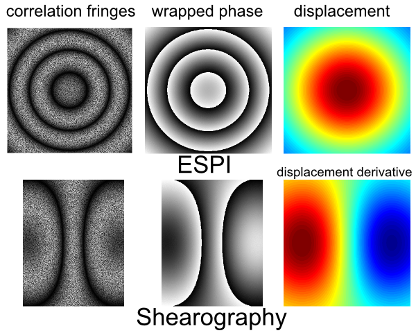 Figure 3 Simulation of the correlation fringe patterns and wrapped phase maps obtained using out-of-plane sensitive ESPI and shearography systems. The object is a flat plate that is clamped around its perimeter and subject to a central load.
Next: Shape and vibration measurement
Further Reading
Holographic and Speckle Interferometry
Jones and C. Wykes
Cambridge University Press, Cambridge, 1989.
Digital speckle interferometry and related techniques
K. Rastogi
Wiley, Chichester, 2001.
Speckle interferometry
S. Sirohi
Cont. Phys., 43:3, pp 161-80, 2002.
Interferogram analysis: digital fringe pattern measurement techniques
W. Robinson and G. T. Reid
Institute of Physics, Bristol 1993.